When a yacht takes on water offshore, the bilge system is the gap between a problem you can manage and one you cannot. Yet most pre-departure checks in Cairns treat it as a background item - pump runs, tick the box, move on. That approach fails to account for two realities specific to Far North Queensland passages. First, the tropical heat, humidity and salt-laden air of Cairns accelerate every known failure mode in a bilge system - float switch corrosion, neoprene valve rot, wiring breakdown - far faster than the same components would degrade in any temperate port. Second, the World Sailing Offshore Special Regulations impose minimum manual pump requirements for Category 1 offshore passages that most cruising sailors have never read and many boats do not meet. This guide examines every component from the electric pump motor to the discharge through-hull, with practical inspection steps and Cairns-specific sourcing.
Why the Bilge System Is a Safety System
A leak at sea is not a maintenance inconvenience - it is a progressive threat. Stuffing boxes weep, hose clamps loosen under vibration, hull fittings corrode, keel bolts seep in a seaway. None of these is immediately fatal. What determines outcome is whether the bilge system detects and removes water fast enough to give the crew time to find and address the source. That is a safety function.
Cairns creates a harsher operating environment than most Australian cruising grounds. Ambient temperatures regularly exceed 30 degrees Celsius, humidity is persistently high, and the salt content of marina air is significant. These conditions accelerate corrosion on electrical contacts and wiring to a degree that would surprise sailors arriving from the south. Corrosion on float switch wiring has been documented within as little as two months of installation in tropical marine conditions - a failure timeline that makes annual inspection wholly inadequate. Add UV degradation of rubber components and the persistent dampness inside a working bilge, and every part of the system is under greater stress than the manufacturer's temperate-climate testing anticipated.
How the Components Work Together
A properly configured offshore bilge system is not a single pump - it is a layered arrangement of detection, response and backup. Understanding how the parts interact helps identify where a failure will cascade and why no single component is sufficient on its own.
- Primary electric submersible pump: removes water automatically at high volume when triggered by a sensor or switched manually from the helm or chart table.
- Float switch or electronic sensor: detects rising water and triggers the primary pump without crew input.
- High-water alarm: an independent circuit, set above the main pump activation level, that alerts the crew when the primary pump has not kept up with incoming water.
- Manual backup pumps: two permanently installed pumps providing capacity when power fails or the electric pump is overwhelmed - a regulatory requirement for offshore passages, not an optional upgrade.
- Strum box and intake strainer: the filter at the pump inlet that keeps debris from jamming the impeller.
- Discharge hose and through-hull: the path water takes to exit the vessel, including an anti-siphon loop where the through-hull placement requires one.
Each component can fail independently. A dead electric pump matters less if the manual pumps are functional. A blocked strum box renders a perfectly functioning motor useless. The system only works when all parts work together.
Sizing the Primary Electric Pump
Bilge pump capacity is stated in gallons per hour (GPH) or litres per hour at zero head - meaning the discharge outlet is at exactly the same height as the pump inlet, with no lift required. That number is never the number you will see in service.
The Head-Height Penalty
The moment the discharge hose rises above the pump to exit through a through-hull, output drops sharply. A pump rated at 2,000 GPH at zero head may deliver only around 1,300 GPH with just three feet of vertical lift in the discharge line. For a yacht with a keel-sump pump and a through-hull a metre above the waterline, this penalty is real and substantial. When comparing pumps, look for performance curves at the actual head height your installation requires - not the nameplate figure alone.
For offshore yachts in the 36 to 50-foot range, the standard recommendation is a primary electric pump delivering at least 4,000 GPH at zero head, with a separate high-capacity backup electric pump wired to a different circuit and, where possible, a separate battery bank. The Rule 3700 - rated at approximately 3,700 US gallons per hour at zero head - is a widely used primary pump in this class. The backup pump on a separate fuse ensures a single electrical fault cannot disable both circuits simultaneously.
| Pump type | Activation | Power required | Practical role |
|---|---|---|---|
| Primary electric submersible | Auto sensor or manual switch | Yes - 12V DC | First response, continuous duty |
| Backup electric submersible | Manual switch, separate circuit | Yes - separate bank preferred | Supplements primary if overwhelmed |
| Deck-mounted manual pump | Manual crew operation | None | OSR compliance; power-loss backup |
| Below-deck manual pump | Manual crew operation | None | OSR compliance; crew-below operation |
Float Switches and Automatic Sensors
The float switch is statistically the most likely component to fail. Stuck or corroded float switches are responsible for roughly half of all bilge pump failures - the mechanical float arm seizes from salt deposit, sediment or corrosion, and the pump never receives a trigger signal. In Cairns's tropical conditions this failure can occur within weeks on a neglected system, not years.
Testing Float Switch Operation
To test a mechanical float switch, physically lift the float arm while the pump is wired and powered. The pump should activate immediately. Release it; the pump should stop. Any hesitation, stickiness or failure to activate is cause for replacement before departure, not investigation. A float switch that works nine times out of ten is not adequate on an offshore passage.
Signs That Call for Replacement Rather Than Cleaning
- Visible corrosion on the terminal pins or wiring connections.
- Stickiness or resistance anywhere in the float arm's travel.
- A float arm that does not return freely when released.
- Wiring insulation showing cracking, brittleness or green oxidation under the sheath.
- Any switch that failed to activate during a test, even once.
Electronic Sensing as an Alternative
Rule automatic pumps using electronic impeller-resistance sensing check the bilge every 2.5 minutes without a mechanical float arm. The sensing circuit detects whether the impeller is in water or air and responds accordingly, eliminating the most common failure point in automatic systems. The tradeoff is a brief motor cycle every few minutes regardless of water level - a minor current draw that is inconsequential for most offshore electrical budgets. For tropical passages where corrosion is a known accelerator, electronic sensing deserves serious consideration alongside or instead of mechanical float switches.
High-Water Alarms
The primary pump and its trigger switch form one loop. The high-water alarm is a second, independent loop set at a higher water level than the pump activation point. Its purpose is to alert the crew when the primary pump has activated, run, and failed to keep up - a situation that demands immediate attention regardless of conditions or watch schedule.
The Rule high-water bilge alarm (model 33ALA, 12V) is commonly paired with the Rule 3700 for this purpose. It includes a separate float switch positioned above the pump switch level. When water rises to that point, the alarm sounds. This arrangement provides a meaningful safety margin: the pump activates at one level, and if water continues rising past it, the alarm fires as a second warning.
Wire the alarm to an independent fuse and route the sounder to both the helm and the main cabin so the signal is heard on watch and below. Test the alarm circuit by manually lifting its float switch at the dock before each offshore departure. Like the pump switch, the alarm switch must be replaced if it shows any corrosion or mechanical resistance - in a tropical climate that check belongs in every pre-passage routine.
Manual Backup Pumps and the World Sailing OSR Requirement
The World Sailing Offshore Special Regulations for Category 1 monohull passages require two permanently installed manual bilge pumps: one operable from above deck with cockpit seats, hatches and the companionway closed, and one operable from below deck under the same conditions. This is a minimum requirement, not a recommendation. Many cruising yachts departing Cairns on bluewater passages fall into Category 1, and many do not currently meet this two-pump standard. The OSR also specify that bilge pump discharge must not enter a cockpit unless that cockpit opens directly and freely aft to the sea - discharge into a sump-drained cockpit is not compliant. These are not paperwork requirements; they reflect lessons from offshore casualties where manual pumping was the only option remaining.
The Whale Gusher Titan
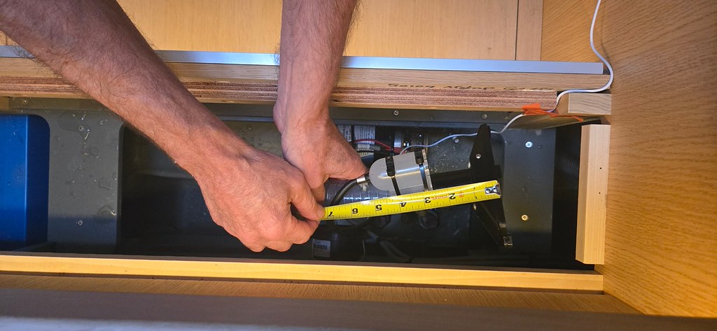
The Whale Gusher Titan is a deck-mounted diaphragm pump rated by the manufacturer as the primary manual pump for yachts of 12 metres and over. It moves water through a 38mm hose at high volume and is designed for sustained operation under load. Installation requires a dedicated through-deck fitting and a discharge hose independent of the electric pump circuit.
Inspecting Diaphragm Valves in a Tropical Climate
The Gusher Titan uses neoprene diaphragms and valve seats that degrade under UV and sustained heat. In Cairns's tropical environment this degradation is faster than the manufacturer's temperate-climate service intervals suggest. Remove the pump head, inspect the diaphragm for cracking or stiffness, and inspect the valve flap seats for deformation before each offshore departure. Replacement diaphragm kits are available; fitting a used or degraded diaphragm to a pump that may be called on in an emergency is a risk that is easy to eliminate at the dock.
Strum Boxes and Intake Strainers
The strum box is the perforated or slotted intake guard at the pump inlet inside the bilge. It prevents debris - rags, hose sections, sawdust, paper, sediment - from entering the pump and jamming the impeller. When the strum box is blocked, the motor runs but moves no water. On a vessel with active water ingress, a blocked strainer allows flooding to progress undetected for hours while the pump appears to be operating normally - one of the more insidious failure modes in the system.
Inspection is straightforward. Remove the strum box completely and rinse it clear of accumulated sediment and debris. Check that all perforations are open - paint, corrosion or crushed metal can partially block flow even when the box looks intact. Confirm the strum box seats securely back on the pump inlet, since a loose fit allows debris around the guard. Also confirm the pump sits low enough in the bilge sump to reach the last standing water - a pump mounted too high will trigger and run dry before the bilge is clear.
World Sailing OSR require all permanently installed bilge pumps to be readily accessible for maintenance and debris clearing. If a pump is sealed behind joinery or unreachable without tools, it fails that requirement and needs to be repositioned or made accessible before the passage departs.
Discharge Routing and Anti-Siphon Loops
The discharge hose path from pump to through-hull matters for two reasons: total head height affects actual pump output, and an incorrectly routed or unprotected discharge line can back-flood the vessel when the boat heels offshore.
Through-Hull Placement and Heel Angle
Bilge pump through-hulls are typically positioned above the waterline when the boat is upright. At significant angles of heel - common in a seaway or during a heavy-weather passage north of Cairns - the same fitting may submerge. If the pump is not running when this happens, water can siphon back through the discharge hose into the bilge and add to the problem rather than remove it.
Anti-Siphon Vented Loops
When the discharge through-hull is positioned close to the waterline at any angle of heel, a vented anti-siphon loop in the discharge hose is the correct solution - it breaks the siphon by introducing air into the line before back-flooding can establish.ABYC guidance on bilge pump discharge installation
ABYC provides a specific proximity threshold for when a vented loop is required - check the current ABYC standards for the exact figure, as the standard may be updated. The loop is installed at the highest point of the discharge hose run, above the heeled waterline. A small vent fitting at the top of the loop allows air in, breaking any siphon. The vent must itself remain above the waterline at the angles the vessel will experience offshore. Check that the vent fitting is clear of salt crystal blockage before departure - a blocked vent provides no protection.
Bilge Cleanliness, the Pre-Departure Sequence, and Cairns Sourcing
Why a Clean Bilge Is a Technical Matter
Oil films, diesel residue, grease and accumulated grime coat float switch mechanisms and prevent activation. A bilge that smells of fuel and shows an oily sheen is a bilge where the automatic pump trigger may not work at the moment it is needed. Clean the bilge thoroughly before testing any automatic sensor, and repeat the cleaning if the boat sits for more than a few weeks between passages. In Cairns, where engine and generator use is heavy during pre-passage preparation and the heat accelerates breakdown of fuel residue into sticky deposits, this cleaning step matters more than in cooler ports.
Pre-Departure Inspection Sequence
- Clean the bilge - remove standing water, oil residue and debris before beginning any electrical testing.
- Remove and inspect the strum box on each electric pump. Clear any blockage and refit securely.
- Test the primary electric pump in manual mode from the helm switch. Confirm flow at the discharge through-hull.
- Test the primary float switch by lifting the float arm manually. Confirm pump activation. Check terminal connections for corrosion.
- Test the high-water alarm by lifting its float switch manually. Confirm the alarm sounds at the helm and in the cabin.
- Inspect the discharge hose run from pump to through-hull. Check hose clamps at both ends. Inspect the anti-siphon vent fitting for salt crystal blockage.
- Test both manual pumps - operate each through several full strokes and confirm flow at the respective through-hull. Note any sponginess or reduced stroke volume that suggests diaphragm wear.
- Remove the Whale Gusher Titan pump head and inspect the neoprene diaphragm and valve seats for cracking, deformation or stiffness.
- Confirm that both manual pumps are operable from their required positions - one from on deck with the companionway closed, one from below - as the OSR requires.
- Log the test, the date, and any components replaced or identified for attention before departure.
Parts and Service in Cairns
HiTune Marine in Cairns stocks bilge pumps and marine plumbing supplies including pump models and fittings suitable for offshore preparation. Cairns Marlin Marina hosts a range of service providers including marine electricians who can wire, test and document bilge pump systems - relevant if OSR-compliant wiring, a new high-water alarm installation or a pump upgrade is needed before departure. Contact suppliers directly for current stock and availability; product lines change and pricing is not something a guide like this can keep current. The World Sailing Offshore Special Regulations document is publicly available on the World Sailing website - read the current edition before departing on a Category 1 passage, as requirements are updated periodically.
Frequently Asked Questions
How often should I replace a float switch on a boat kept in Cairns?
In tropical Far North Queensland conditions, annual replacement is a reasonable baseline for mechanical float switches - and inspection every few months if the boat is used heavily or sits in a hot marina berth. Corrosion on float switch wiring has been documented within two months in tropical marine environments, so the temperate-climate guidance of replacing every two or three years does not apply here.
Can I use my existing cockpit bilge pump to meet the World Sailing OSR manual pump requirement?
Only if the cockpit it discharges into opens directly and freely aft to the sea. If the cockpit has a sump and drain system, discharging bilge water there is not compliant. Beyond that, OSR requires one pump operable from on deck with the companionway closed and one from below - a single pump in one position does not satisfy both conditions.
What is an anti-siphon vented loop and do I actually need one?
It is a high point in the bilge pump discharge hose with a small air vent at the top, designed to prevent water siphoning back through the discharge line into the bilge when the through-hull submerges at heel. If your discharge through-hull comes close to or below the waterline at any angle of heel, a vented loop is the correct installation. Many older boats lack this fitting - check the hose run against the vessel's heel angle before passage and refer to current ABYC standards for the specific installation threshold.
My bilge pump runs but seems to clear the bilge slowly. What should I check first?
Check the strum box first - a partially blocked strainer dramatically reduces actual flow even when the motor is running at full power. After that, consider the head height from the pump to the discharge through-hull and compare it against the pump's performance curve at that lift, not the zero-head nameplate figure. A pump that appears undersized may simply be working against more discharge head than its rating implies.
Are electronic sensing pumps more reliable than float switch models in tropical conditions?
Electronic sensing eliminates the mechanical float arm, which accounts for the majority of automatic bilge pump failures in salt environments. For a tropical climate like Cairns, that is a meaningful advantage. The tradeoff is that the pump motor cycles briefly every few minutes regardless of water level, drawing a small continuous current. For most offshore boats with adequate battery capacity this is an acceptable tradeoff for removing the highest-probability failure point from the system.
How do I confirm my manual pump installation actually meets the OSR before leaving Cairns?
Test each pump physically with the cockpit seats in place, hatches closed and the companionway boards and washboard fully in position - then pump from on deck with everything shut. Repeat from below under the same conditions. If either position is not workable, the installation needs to change before departure. The World Sailing OSR document on the World Sailing website details Category 1 requirements in full and is the authoritative source - not chandlery advice or secondhand summaries.